The Speed Search function allows the drive to detect the speed of a rotating motor shaft that is driven by external forces (e.g. fan rotating by windmill effect or motor driven by load inertia). The motor operation can be directly started from the speed detected without needing to stop the machine before. Example: When a momentary loss of power occurs, the drive output shuts off. This results in a coasting motor. When power returns, the drive can find the speed of the coasting motor and restart it directly. The drive offers two types of Speed Search, Speed Estimation and Current Detection. Both methods are explained below followed by a description of all relevant parameters.
Before Starting the Motor
Check the following items before operation:
• Ensure the area around the motor is safe.
• Ensure external emergency stop circuitry is working properly and other safety precautions have been taken.
During Operation
Check the following items during operation:
• The motor should rotate smoothly (i.e., no abnormal noise or oscillation).
• The motor should accelerate and decelerate smoothly.
No-Load Operation Instructions
The following example illustrates a test run procedure using the digital operator.
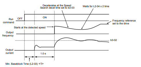
This method can be used for a single motor connected to a drive. It should not be utilized if the motor is one or more frame sizes smaller than the drive, at motor speeds above 130 Hz, or when using a single drive to operate more than one motor. The Speed Estimation type distinguishes two kinds of operation, Back EMF voltage estimation and DC current injection.
This method is used by Speed Search after short Baseblock (e.g. a power loss where the drives CPU kept running and the Run command was kept active). Here the drive estimates the motor speed by analyzing the back EMF voltage. It outputs the estimated frequency and increases the voltage using the time constant set in parameter L2-04. After that the motor is accelerated or decelerated to the frequency reference starting from the detected speed.
The unit plan for the operation of the main control is as follows.
Load command distribution center – selects which boilers participate in load regulation based on their operating status; – The rate of change of limit load instructions; – The corresponding load command is output by the main pipe pressure regulator; – Control instructions for each boiler formed by load distribution; Determination of load distribution coefficient: Based on the physical location and operating conditions of the boiler and steam turbine, the determination of load distribution coefficient can be divided into several situations. The principle for determining load distribution coefficient is: the distance between the boiler and the turbine is the shortest, and the loss of thermal load is the smallest. Calculate the load distribution coefficient based on the distance between the steam pipelines of the turbine and boiler and the amount of steam loss. Therefore, the shortest distance coefficient between the boiler and the turbine is 1, which means the closest boiler has the largest supply of steam to the nearest turbine. When the unit is partially operating, the above principles are still used to determine the load distribution coefficient of the operating unit.


There are no reviews yet.