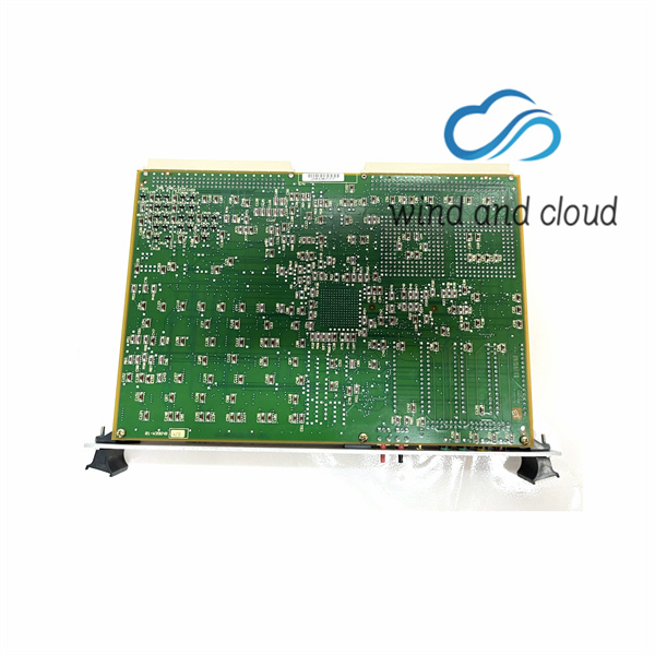
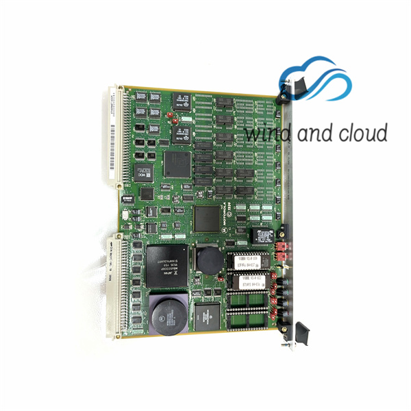
This manual, MVME147 MPU VMEmodule Installation and Use, provides general information, hardware preparation and installation instructions, operating instructions, programming information, functional description, and debugger firmware information for the MVME147 MPU VMEmodule. The information contained in this manual applies to the following MVME147 models: This manual is intended for anyone who wants to design OEM systems, supply additional capability to an existing compatible system, or work in a lab environment for experimental purposes. A basic knowledge of computers and digital logic is assumed.
MVME147-010
MVME147-011
MVME147-012
MVME147-013
MVME147-014
MVME147-022
MVME147-023
MVME147-024
The VMEchip Global Control and Status Register (GCSR) Set appears at odd addresses in the VMEbus short I/O memory map. A map decoder in the VMEchip monitors the address and the address modifier lines and requests the VMEchip global registers when they are selected. Note that the GCSR can only be accessed in Supervisor Data Space; no User Mode accesses are available.
The VMEbus distinguishes interrupt acknowledge cycles from other cycles by activating the IACK* signal line. It also specifies the level that is being acknowledged using A03-A01. The VMEchip monitors these lines and after receiving IACKIN*, it responds by asserting IACKOUT* if it was not generating an interrupt at the acknowledged level, or by returning a status/ID vector if it was. The MVME147 may handle a VMEbus interrupt generated by its own VMEchip





There are no reviews yet.