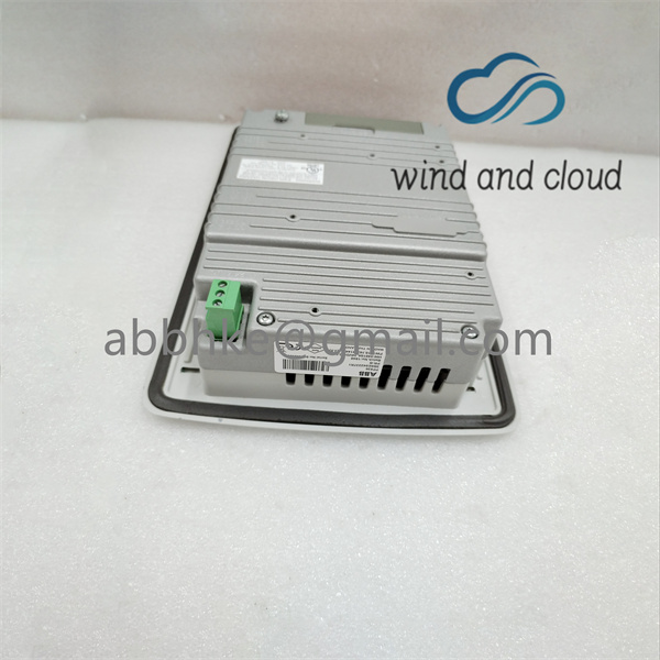
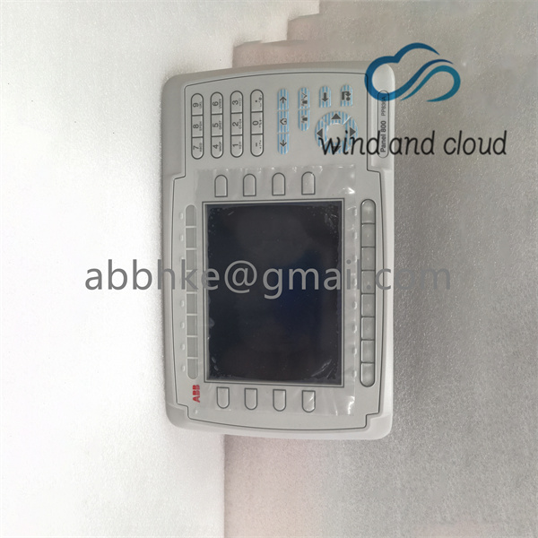
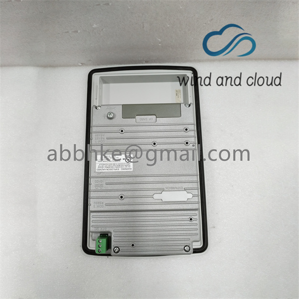
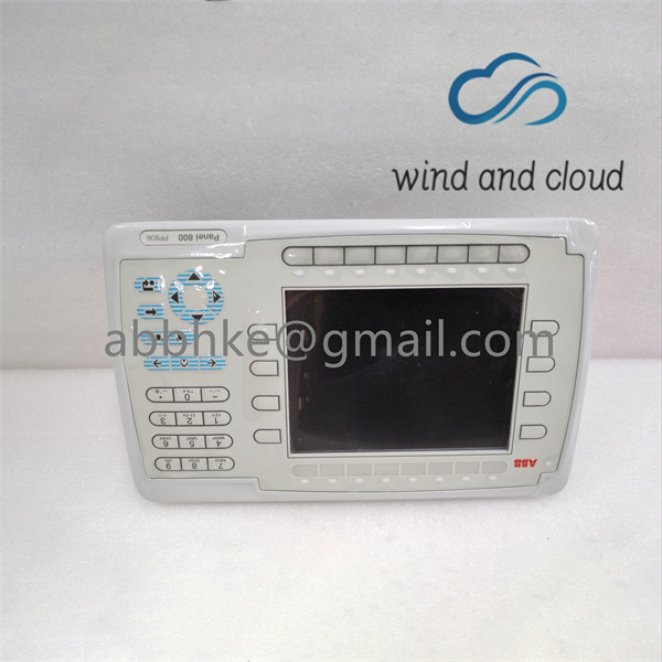
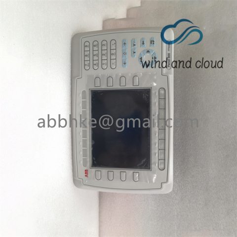
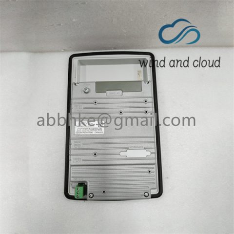
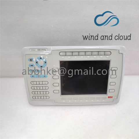
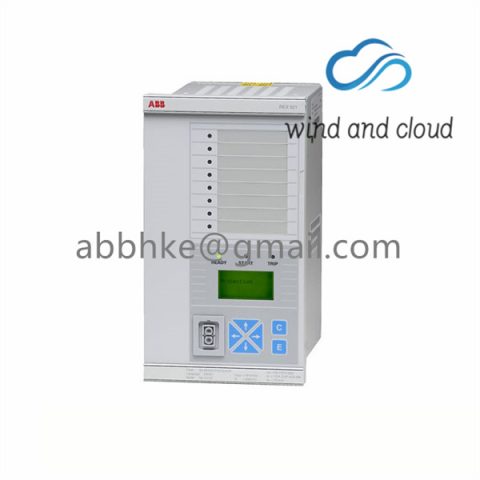
PP836 ABB terminal interface device
A TB850 male CEX-Bus termination unit is supplied with each package (PM851K01, PM851AK01, PM856K01, PM856AK01, PM860K01, PM860AK01, PM861K01, PM861AK01, PM864K01, PM864AK01 and PM865K01) of the PM8xx/TP830 processor unit.
The control network connects to one or two RJ45 connectors (CN1 and CN2) depending on network option (single or redundant). Use an RJ45 connector for IEEE802.3 (Ethernet) for connecting to a category 5 Shielded Twisted Pair cable (STP class 5). The connection to the optical ModuleBus is identical to that for the processor unit and for the FCI in S800 I/O (see Figure 54 on page 160.) Class 5, or higher, cable 10/100BaseT/TX max 100 m (110 yd). ABB recommends the use of optical fiber in an industrial environment, for example 62.5/125 100BaseFX, max. distance 1500 m (1600 yd).
In redundant configuration, two PM891 units are mounted on two separate DIN-rails. If sufficient space is available, the units can be mounted on the same DIN-rail. Use the following procedure to install the processor units along the DIN-rail:
1. Mount the processor units.
2. Mount the communication interfaces on the CEX-Bus to the left of the processor unit. If BC810s are used, the configuration of the segments should be considered. If no BC810s are used, the interfaces can be divided between the two CPUs in any preferred way.
3. Press the units gently together and ensure that the CEX-Bus is correctly connected, through the connector on the unit.
4. If BC810s are used, connect the TK851 cable to the two BC810s. If no BC810s are used, mount the CEX-Bus extension cable TK850 to the units at farthest away from the processor units or, if no units are mounted, directly to the CEXBus on the processor unit. The CEX-Bus extension cable must be connected to both CPUs whether or not there are any other CEX-Bus units (Figure 29 on page 93).
5. Connect the RCU Data Link Cable (TK855) and the RCU Control Link Cable (TK856) to both CPUs.
The RCU Data Link Cable (TK855) and the RCU Control Link Cable (TK856) must not be replaced by similar cables. Using another cable will disable the identification of the CPUs in the Control Builder and Operator Station. The CPU connected to the RCU Control Link Cable (TK856) connector marked “UPPER” will be defined as “UPPER” in the Control Builder and Operator Station. The marking has no relevance to the physical placement of the CPUs. Any CPU can become the Primary CPU.
Today’s special offer
Brand new original stock available at a special price
TRICONEX: 3625, 3721, 3664
ABB: 5SHX1060H0003, DSQC679, SPHSS13, 3BSE008105R1 SC560, 3BSE012545R1 CI546
Rockwell ICS modules: T8403, T8461, T8110, T8110B
Emerson: VE3007, VE3008 old models, CE3008, CE3007 new models
GE: IC698RMX016

 Can be calibrated on the same day
There are no reviews yet.