The module has a resolution of 12 bits. This corresponds to 4096 possible measured values.
With a measuring range of 0…20 mA, this results in a resolution of 4,88 μA/bit.
The module can output much more precise values than the 12-bit resolution allows by using suitable algorithms (moving
averages, etc.). With PG5 and QronoX, a measuring range of 0…20 mA with a resolution of 1 μA is achieved as standard.
In the configurator you can choose whether you want to use the measurement results in μA or in bits.
A user-defined range can also be displayed for special applications. The user can make specifications:
f Lower value: Displayed value with an input signal of 0 mA.
f Upper value: Displayed value at an input signal of 20 mA.
Any integer value (–32’768 up to +32’767) can be entered for both values, but the lower value must be smaller than the upper
value. However, to avoid error messages when outputting in the extended range (–1% up to +110%), the following values
should be used:
f Lower value: greater than –32’440
f Upper value: less than +29’490
All values in between are converted directly proportional to these two basic values and indicated as measured value.
The hardware performance of the A-B PLC is relatively stable, so there are few faults in the dry ice line PLC. Generally, there are the following types:
1. The analog input quantity is displayed as a certain value and does not change. One situation is that it occurs before starting the machine. When encountering this situation, first check whether the red light of the analog input module lights up. If it lights up, turn off the power and switch the module to check if it is burned out. If it is damaged, replace it, If it is not broken or the light is not on, it is a data transmission fault or scanning fault. In this case, the PLC can generally be restored by re powering on. Another type occurs during operation, which is usually caused by a malfunction of the CPU module and analog module. Sometimes, it can be restored even after being powered on again. If it cannot be restored, it may be due to a faulty CPU module.
2. If the operation command is not executed, that is, the operation will not work. There are generally two possibilities in this situation. One is that the conditions that the operation should have are not met, so the operation will not be executed. Another type is when the program is in its own closed loop, such as dead loop or scan time overflow, causing output suppression or communication failure. In this case, the system can be stopped and restarted first, or the system can be powered off and then turned to automatic and started to recover. If it cannot be recovered, the PLC can generally be restored by powering on again.
3. All outputs of the PLC are missing, that is, the indicator lights on the modules corresponding to all points that should have outputs are not lit. There is only one possibility of this fault, which is that the 24 volt power supply provided by the output module is no longer available. One possibility is that the conditions for the intermediate relay to provide power to the output module to engage are not met. Another possibility is that the coil of the intermediate relay is burned or the contact is poor.
4. The signal is delayed and cannot be received, resulting in a control unit being unable to operate. This situation belongs to communication failure or data transmission failure, and generally, the steps for generating the signal can be redone again to recover.
5. All input and output modules of the PLC do not have green lights on. When encountering this situation, the first thing to check is whether the input of the power module has 220V AC power. If not, check the quality of the power supply transformer. If so, it indicates that the power module is faulty.
6. During operation, the online equipment suddenly stops working, meaning that the PLC suddenly “crashes”. In this situation, the first thing to check is the status of the PLC. If all the lights on the modules are not on, it is highly likely that the power module of the PLC is broken; If the lights on all modules turn on again when pressing the CPU with your fingers, then unplugging the CPU and then plugging it in after power outage is normal for troubleshooting. Another situation is that the input and output points of certain input and output modules are not displayed. In this case, when troubleshooting input and output module faults, unplugging and plugging the CPU can generally eliminate the fault.
7. The DH+or COMM light on the CPU is flashing or red, indicating a communication failure. One situation is when the DH+cable is broken or the socket is loose, check and handle the DH+cable and socket until the fault disappears; Another situation is that the communication address of the CPU is incorrect or has been changed. At this time, you must enter RSLinx and click on the communication configuration icon to reconfigure the address of the upper computer or PLC icon with a red cross until the red cross disappears. In short, in the actual production process, various PLC faults will also be encountered.
Although the hardware performance of A-B PLC is relatively stable and the possibility of faults is very small, for our electrical maintenance personnel, whether it is A-B PLC or Siemens PLC, as long as we use it, we must master it. We are always lagging behind in the knowledge of software and hardware of PLC programmable controllers. Only by continuously learning and mastering some maintenance methods and common troubleshooting methods of PLC, can we make PLC better serve us.
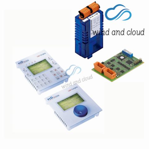
Related model recommendations:
PCD7.F750
PCD7.D202
PCD4.W100
PCD4.N210M4
PCD4.B900
PCD1.M110
PCD1.M120
PCD2.A400
PCD2.A460
PCD2.E110
PCD2.E111
PCD2.E160
PCD2.F520
PCD2.M110
PCD2.M110D162
PCD2.M120
PCD2.M150
PCD2.M480
PCD2.W340
PCD2.W400
PCD2.W410
PCD2.M5540
PCD3.A251



There are no reviews yet.