
-480x480.jpg)

The external control unit and its mounting template are delivered in a cardboard box inside the drive module package. The mounting template contains a mounting pattern for two different control units, one on each side. Make sure to use the ZCU-14 control unit mounting pattern.
1. Mark the positions of the fastening screws to the wall through the mounting template.
2. Attach the screws.
3. Lift the control unit onto the screws and tighten the screws.
One control panel(or PC) can be used to control several drives (orinverter units, supply units etc.) by constructing a panel bus. This is done by daisy-chaining the panel connections of the drives. Some drives have the necessary (twin) panel connectors in the control panel holder; those that do not require the installation of an FDPI-02 module (available separately). For further information, see the hardware description and FDPI-02 diagnostics and panel interface user’s manual (3AUA0000113618 [English]).
The maximum allowed length of the cable chain is 100 m (328 ft).
1. Connect the panel to one drive using an Ethernet (for example Cat 5e) cable.
• Use Menu – Settings – Edit texts – Drive to give a descriptive name to the drive
• Use parameter 49.01* to assign the drive with a unique node ID number
• Set other parameters in group 49* if necessary
• Use parameter 49.06* to validate any changes.
*The parameter group is 149 with supply (line-side), brake or DC/DC converter units. Repeat the above for each drive.
2. With the panel connected to one unit, link the units using Ethernet cables.
3. Switch on the bus termination on the drive that is farthest from the control panel in the chain.
• With drives that have the panel mounted on the front cover, move the terminating switch into the outer position.
• With an FDPI-02 module, move termination switch S2 into the TERMINATED position. Make sure that bus termination is off on all other drives.
4. On the control panel, switch on the panel bus functionality (Options – Select drive – Panel bus). The drive to be controlled can now be selected from the list under Options – Select drive.
If a PC is connected to the control panel, the drives on the panel bus are automatically displayed in the Drive Composer PC tool.
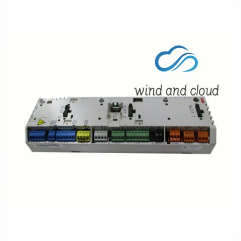
.jpg "ZCU-14 3AXD5000005164 ABB Subject to any electromechanical contactillustration")
A PC (with, for example, the Drive composer PC tool) can be connected as follows:
1. To connect a control panel to the unit, either • insert the control panel into the panel holder or platform, or • use an Ethernet (eg, Cat 5e) networking cable.
2. Remove the USB connector cover on the front of the control panel.
3. Connect an USB cable (Type A to Type Mini-B) between the USB connector on the control panel (3a) and a free USB port on the PC (3b).
4. The panel will display an indication whenever the connection is active. 5. See the documentation of the PC tool for setup instructions.
There are no reviews yet.